 CN
CN EN
EN
Direct operated transmission refers to a type of transmission where the driver can directly manipulate the control lever of the transmission to shift the internal shift mechanism of the vehicle. It is widely used in most small cars and long head trucks (such as pickup trucks)
Direct operated transmission refers to a type of transmission where the driver can directly manipulate the control lever of the transmission to shift the internal shift mechanism of the vehicle. It is widely used in most small cars and long head trucks (such as pickup trucks). Direct operated transmissions have the characteristics of high transmission efficiency and cost advantages, but the difficulty in controlling vehicle vibration and poor shifting sensation of direct operated transmissions are also important factors that constrain their development. Here is an introduction to a method to improve the shift suction sensation of direct operated transmissions, hoping to make a small attempt and push forward the development of direct operated transmissions.
The unique control mode of direct control transmission requires that the control lever and all shift control devices of the transmission must be set on the transmission cover, while the transmission must be arranged near the driver's seat to achieve its functions. It is precisely this unique structure that causes space congestion and large accumulated gaps in the layout of the transmission's shift mechanism. As a result, the overall shifting sensation of the transmission is poor, and there is little room for improvement. In response to the above problems, we have continuously tried and finally solved the problem of poor shifting suction sensation by adding a shift block and positioning pin to the mechanism. At the same time, we have reduced the idle stroke ratio of the shift and significantly improved the shifting sensation. Firstly, learn about a gear selection and shifting mechanism that directly controls the transmission, as shown in Figure 1.
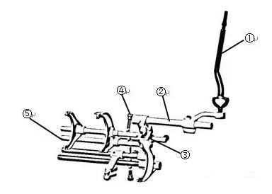
Note: ① Control lever ② Shift shaft assembly ③ Shift blocks for each gear ④ Self locking spring ⑤ Shift fork shaft and fork for each gear
Figure 1 shows the selection and shift control mechanism of an Aisin direct operated transmission. The mechanism shifts gears through the transmission sequence of ① control lever - ② selection and shift shaft assembly - ③ shift block - ⑤ shift fork shaft and fork. It can be seen in the figure that the ball head of the control lever is first connected to the selection and shift arm, and then connected to the shift blocks of each gear through the selection and shift shaft assembly. Each shift block is then transmitted to the shift fork and synchronizer gear sleeve, Through our mapping of the actual mechanism, the gap accumulated during this process is about 1.5mm. If we calculate the lever ratio of 6 to the cab ball head, the idle stroke reaches 9mm, accounting for 10% of the total stroke, which is a bad impact on the shifting feeling. In this mechanism, the force acting on the driver's hand mainly comes from the ④ self-locking spring force, synchronizer spring force, and frictional resistance of various transmission mechanisms in the mechanism.
In order to effectively improve the above issues, we have added a shift block to the selector shaft assembly and a positioning pin to the original control seat (the application of positioning pins has been successful in many models of passenger cars and commercial vehicles), as shown in Figure 2 below
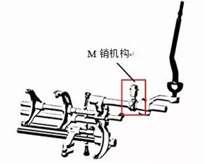
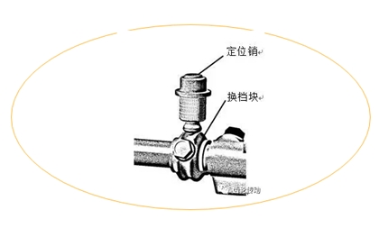
Figure 3 is a partial enlarged view of the M-pin mechanism in Figure 2. By adding the shift block in Figure 3, the original design can be optimized in the following aspects:
1. As mentioned earlier, the control transmission sequence of the original mechanism and the existence of gaps between various components can be included in the design of the shift block. By adding a shift block, we can incorporate the gap between the shift head and shift block, as well as the gap between the shift fork and gear sleeve, into the stroke design of the shift block. This allows drivers to only feel the gap between the control lever and the selector arm during operation, which can be designed to be very small.
2. In order to ensure the overall shifting force of the transmission, we must reduce the force in the original mechanism. In the research process of optimizing the gear shifting performance of the original mechanism, we conducted an actual verification, which was to increase the stiffness of the self-locking spring without making any other adjustments to the mechanism. Through actual measurements, we found that in addition to the influence of spring force on the mechanism, the frictional resistance of the system also increased. On the contrary, when we reduce the self-locking spring force, the frictional resistance of the system will also decrease, which is excellent for the composition of force in the mechanism.
3. The addition of shift blocks has provided a precise positioning of the neutral position of the gear selection and shifting mechanism, and the phenomenon of gear selection jamming has been greatly improved compared to before the improvement. It can be said that it has completely avoided the slight gear selection jamming caused by operation or machining errors, which is something we love to see.
So what elements should be paid attention to in the design process of the shift block and positioning pin? In summary, there are roughly two points:
1. The main design essentials of the shift block are actually the common M-slot design concept. The design should consider several factors of force during the shift process comprehensively. From the previous Figure 2, it can be clearly seen that each acting force plays a role at that node. The role here is nothing more than assistance and resistance. For example, the shift block is resistance during the climbing phase and assistance during the downhill phase, And the friction or drag force of the system always plays a role in resistance. If there are also M grooves on the shift fork shaft of each gear, it should also be considered that the nodes of each force should be designed reasonably, and it cannot be counterproductive. Here, a concept is introduced, which is called the travel ratio between the positioning pin climbing and downhill, hereinafter referred to as the travel ratio. For example, when designing the M groove of the shift block, full consideration should be given to the stroke ratio of the M groove on the shift fork shaft. The design principle is preferably that the stroke ratio on the shift fork shaft is slightly smaller than the stroke ratio of the shift block. In addition, the force effect of the synchronizer during the shift process should also be comprehensively considered. Only when the relevant force designs are appropriate, can the suction force during the shift and downshift be substantially helpful.
2. The design of the positioning pin should pay special attention to interference on the shift block, and sufficient drawing simulation and verification work should be done during the design process.
Obviously, by adding shift blocks and positioning pins to the original mechanism, the selection and shifting performance of the direct operated transmission has been greatly improved. However, in the transmission assembly, there are many factors that affect the shifting force. In our research process, we also found that there are many other details that need to be further studied and innovated, and we will continue to explore in this field, Share with everyone the gains brought by technological innovation.
