 CN
CN EN
EN
1. The gearbox is one of the most critical components of wind turbines, with a very harsh working environment. It is difficult to predict the size and direction of the load it will withstand during operation, and the large uncertainty of instantaneous loads and time-varying variable amplitude alternating loads can easily lead to faults in wind turbines. As the main transmission component of wind turbines, The gearbox is currently one of the most prone components to malfunctions in wind turbines.
Wind turbines are generally installed in remote areas such as wilderness, mountain passes, and the seaside. The components such as the gearbox and generator are also installed in a narrow engine room several tens of meters above the ground. Due to limited space in the engine room, harsh environment, inconvenient transportation, and the difficulty of repairing the gearbox once it malfunctions. Additionally, if the gearbox cannot be repaired on the tower and needs to be removed from the tower, the maintenance cost is high, And the entire maintenance cycle is long, which will seriously affect the economic benefits of the wind farm. Therefore, reducing the probability of wind power gearbox failure and providing easy maintenance for wind power gearbox will be a key consideration in the design and operation maintenance process of wind power gearbox.
This article will start with common faults in wind power gearboxes, analyze the causes of faults and their influencing factors, and propose issues that should be noted and measures that can be taken in the design optimization, production, operation and maintenance process of gearboxes for reference.
2. Common faults and cause analysis of gearbox
Common faults of wind power gearbox include gear damage, bearing damage and abnormal operation, shaft breakage, oil leakage, gearbox abnormal noise, large vibration, abnormal oil temperature and pressure, damaged connecting bolts, lubrication system faults, etc.
2.1 Gear damage
Gear damage mainly includes tooth breakage (tooth breakage), tooth surface fatigue (pitting), tooth surface adhesion, tooth surface wear, etc. The observation results or reports on the failures of gears in gearboxes are relatively consistent both domestically and internationally, that is, the most common occurrence is still the damage to the tooth surface, ranging from micro pitting corrosion in the early stages of application to gradually expanding large-scale pitting, peeling, or wear.
Broken teeth are often formed by the gradual expansion of small cracks. Sudden gusts or power grid failures can cause sudden loads, emergency braking in the event of a malfunction, and can generate significant loads, sometimes even exceeding the rated load several times, causing gear overload and breakage; In addition, bearing damage, shaft bending, or large hard objects squeezing into the meshing area can also cause impact fracture of the gear teeth; Defects in gear materials, pitting, peeling, or other stress concentrations that cause excessive local stress, or large hard foreign objects falling into the meshing area, can cause gear fracture. There are situations in the planetary stage, low-speed intermediate stage, and high-speed stage of the wind power gearbox, with gear tooth breakage being the most severe. Once tooth breakage occurs, most gearboxes need to be repaired from the tower. The broken teeth of the gear are shown in Figure 1.
Numerous studies and observations have shown that micro pitting corrosion mainly occurs in the low-speed stage, while it rarely occurs in other stages. The reason for its occurrence is generally believed to be related to the frequent changes in speed and load of the wind power gearbox. In addition, the roughness of the tooth surface and the cleanliness, water content, viscosity, and oiliness of the oil also have a direct impact on the occurrence of micro pitting corrosion. Insufficient lubrication of tooth surfaces often worsens the lubrication state between tooth surfaces, thereby exacerbating the occurrence of tooth surface friction and micro pitting corrosion. Insufficient design of gear strength, inadequate quality of gear heat treatment, and insufficient hardness of tooth surfaces can all lead to the occurrence of tooth surface pitting. The tooth surface pitting is shown in Figure 1.
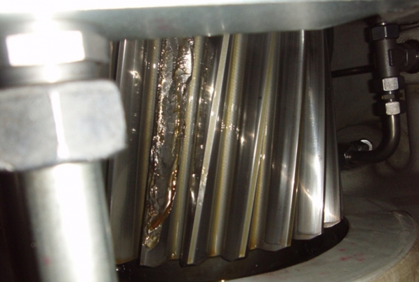
Figure 1 Gear breakage and tooth surface pitting
The occurrence of adhesion on the tooth surface may be due to insufficient lubrication, which leads to an increase in temperature in the meshing area and lubrication failure. The two tooth surfaces adhere to each other, resulting in adhesion; Planetary class low speed and heavy load, the oil film between the tooth surfaces is not easy to form or be damaged, resulting in adhesion.
The main reason for tooth surface wear is that the lubrication system filter element cannot be replaced in a timely manner, resulting in dirty lubricating oil, iron filings, impurities, etc. entering the tooth surface with the lubricating oil, leading to tooth surface wear
2.2 Bearing damage
Due to the particularity of wind turbine operation and the complexity of loads, bearings are a relatively weak link in wind turbine gearboxes. Statistical data shows that early failures in wind power gearboxes were mostly caused by bearings. With the increase of on-site experience, the number of faults caused by bearings has significantly decreased, but they still account for a certain proportion of gearbox failures, and their failure often leads to catastrophic damage to gearboxes. Due to factors such as improper selection, installation deviation, and insufficient lubrication, it is extremely easy to cause bearing burning, damage to the surface of the raceway such as pitting, cracks, surface peeling, and abnormal bearing temperature. The main influencing factors for bearing damage and abnormal operation (rapid temperature rise, large temperature difference between front and rear bearings) include improper selection of initial clearance and fit, deformation of adjacent components (bearing seat, shaft) leading to changes in clearance; The lubricating oil quantity is too small due to small nozzle diameter, low oil pressure, improper nozzle position design, etc; Improper selection of bearings, resulting in bearing slipping due to the inability of the bearing to meet the minimum radial load requirements; Improper design of oil return holes, resulting in stagnant oil return, resulting in poor oil return; Dirty lubricating oil, iron filings, impurities, etc. enter the raceway with lubricating oil, leading to bearing wear.
There are many cases of damage to the high-speed shaft bearings in the gearbox. If the high-speed shaft cannot be replaced on the tower or if the bearings (planetary carrier bearings, planetary gear bearings, etc.) in other parts of the gearbox are damaged, the gearbox must be removed from the tower for maintenance.
2.3 Gearbox leakage
The leakage of oil in the gearbox mainly occurs at the joint surface between the gearbox and the gear ring, the joint surface between the end cover and the gearbox, the journal of the low-speed and high-speed shafts, and the pipe joint of the lubrication and cooling system. The possible reasons for oil leakage on the joint surface of the box and the gear ring include loose bolts connecting the box and gear ring, improper design of the ring groove for installing sealant strips on the joint surface of the box and gear ring, and improper selection of sealant strips. The main reasons for oil leakage and leakage at the low-speed and high-speed shaft journals of the gearbox are improper sealing structure design, which leads to poor oil return, the use of contact sealing with packing, the blockage of the oil return hole caused by worn packing, and improper selection of sealing components. The main reasons for oil leakage at the lubrication system pipe joints are loose or not tightened pipe joints, failure to apply sealant during pipe joint installation, and poor sealing effect of the pipe joints themselves. As shown in Figure 2, the high-speed shaft sealing structure has a certain risk of oil leakage. The oil thrown out by the oil throwing ring is easy to adhere to the surface of the end cover, which may cause oil to drip back onto the shaft from the end face. In addition, the sealing element (packing) is prone to wear, and the worn particles and debris entering the oil return channel can easily block it, thereby affecting the oil return and causing the high-speed shaft to leak oil.
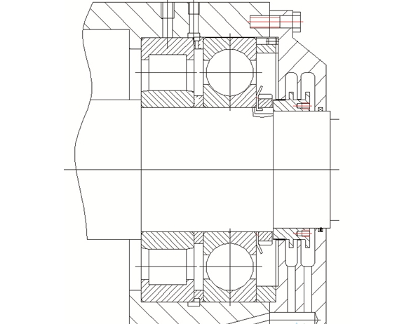
Figure 2 High speed shaft sealing structure of a certain gearbox model
2.4 Abnormal noise and large vibration of the gearbox
The total vibration of the gearbox is accompanied by abnormal noise. There are many cases of abnormal noise and large vibration in the gearbox, and the analysis of the causes of abnormal noise and vibration is relatively complex. However, it can be determined that the following factors may cause abnormal noise and large vibration in the gearbox: low machining accuracy of gear components and the gearbox, and large assembly errors of various components; The gearbox body has low strength and insufficient shaft stiffness, which leads to deformation of the gear shaft and affects the meshing of the gears to produce abnormal noise and vibration; The gear transmission greatly reduces the meshing accuracy of gears due to friction, wear, fatigue pitting, and peeling, and also produces abnormal sounds and vibrations.
2.5 Abnormal gearbox oil temperature and pressure
The abnormal oil temperature and pressure in the gearbox are mainly manifested in high oil temperature, high or low oil pressure, etc. The main factor contributing to the high oil temperature in the gearbox is insufficient cooling capacity design of the cooler; Improper design of ventilation structure in the main engine compartment, resulting in poor ventilation effect in the compartment, resulting in high gearbox temperature; The temperature control valve of the lubrication system malfunctions, and the gearbox lubricating oil enters the gearbox directly without passing through the cooler; The abnormal lubrication oil pressure of the gearbox is influenced by factors such as lubrication system branch failure and lubrication system failure. Lubrication system faults mainly include problems with temperature control valves, resulting in high gearbox oil temperature, mechanical pump failure to pump oil, lubrication system motor failure, and oil pump motor overload (low temperature, high viscosity).
2.6 Others
2.6.1 Damaged gearbox connecting bolts
The damage to the connecting bolts of the gearbox mainly occurs at the connection between the gearbox and the gear ring, and the main form of damage is bolt fracture. The main influencing factor is the impact load on the gearbox; Quality issues with the bolts themselves (poor overall heat treatment effect of the bolts and defects in surface quality); The bolt is loose or not tightened according to the specified torque, resulting in the bolt being cut during operation;
2.6.2 Broken threading pipe
The power and signal lines in the hub of the wind turbine need to pass through the hollow tube of the gearbox and be connected to the slip ring unit, so the failure of the hollow tube will affect the normal operation of the entire machine. The failure of the hollow tube is mainly manifested in the fracture of the hollow tube, which mainly occurs in the welding part between the hollow tube and the bearing installation journal (position I in Figure 3). The main reason for the fracture is that the welding quality of the hollow tube does not meet the requirements (such as welding overlap, undercut, burning through, incomplete welding, slag inclusion, porosity, welding cracks, and weld shape and size not meeting the requirements), resulting in the fracture of the hollow tube during operation. After the fracture occurs, the gearbox needs to be removed from the tower for maintenance.
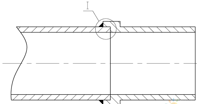
Figure 3 Structure of Hollow Pipe Section
2.6.3 Gearbox paint detachment
The paint peeling off of the gearbox is mainly manifested in the external paint of the gearbox. The paint peeling off on the outer surface of the gearbox mainly occurs on the surface of the shrink disc and gear ring inside the gearbox. The main reason is that the surface smoothness of the shrink disc and inner gear ring is high, and the paint adhesion cannot meet the requirements.
2.6.4 Rust on internal gears of the box
The gearbox has been stored for a long time, and the anti rust oil film on the internal gear parts of the gearbox is damaged and loses its anti rust function, resulting in rust on the surface of the gear parts. The rust is relatively mild and can be removed by running in. For gear boxes with severe rust, the gearbox needs to be opened for rust removal;
2.6.5 Box cracking
Under low temperature conditions, the gearbox is subjected to impact loads, resulting in cracking of the gearbox body or gear ring. The main reason is that the material itself or the heat treatment cannot meet the requirements, resulting in brittle fracture at low temperatures.
3. Design and operation maintenance suggestions for wind power gearbox
In response to the above-mentioned problems in wind power gearboxes, it is required that corresponding measures must be taken during the design, operation and maintenance process of gearboxes to reduce the probability of these problems. Below, relevant suggestions will be proposed for reference from the design, operation and maintenance aspects of gearboxes.
3.1. Precision machining and shaping of gear components
Research has shown that lower surface roughness has a significant impact on suppressing the generation of micro pitting corrosion on tooth surfaces, improving lubrication conditions between tooth surfaces, reducing wear, reducing friction, extending the operating life of gear pairs, and enhancing the ability to resist corrosion fatigue.
At present, the surface roughness requirement for gear components in China is Ra0.8, even lower than this requirement. It is reported that the final tooth surface roughness can reach Ra0.2~0.4 in foreign countries, which is not yet adopted in China. It is recommended that gearbox manufacturers make full use of existing technological means, by changing grinding media and process parameters, and adopting precision grinding methods as close as possible to the above goals, in order to provide hardware guarantees for stable mass production of high-performance wind power gearboxes.
In addition, improving the machining accuracy of gear components and using advanced technology and software for gear modification can avoid gear deformation under load during transmission, reduce eccentric load, make the load transition smooth, and significantly reduce the noise and vibration of the gearbox.
3.2 Optimization design of gearbox
The failure of high-speed shaft components accounts for a high proportion of wind power gearbox failures, and is a component that is prone to failure in the gearbox. If the high-speed shaft does not have detachable conditions, the gearbox can only be repaired from the tower after the failure of the high-speed shaft components, and the maintenance cost and maintenance cycle will increase. Therefore, in the design process of the gearbox, the high-speed shaft components must have detachable conditions. In the early design of gearboxes, most high-speed shafts did not have the conditions for disassembly. In the subsequent product maintenance process, the high-speed shaft unit needs to be further optimized to make the high-speed shaft detachable.
With the development of offshore wind power technology, higher requirements have been put forward for wind power gearboxes. Due to the high maintenance cost of offshore wind turbines, it is required that in addition to high-speed shaft components, other components also have detachable conditions. Therefore, the modular design requirements for wind power gearboxes will be increasingly strengthened.
Due to quality issues with bolts, it is common for the connecting bolts of the gearbox box and inner gear ring to break. If the connecting bolts are damaged and cannot be replaced in a timely manner, it will affect the normal operation of the gearbox. Therefore, it is required that the external connecting bolts of the gearbox must have the conditions for disassembly, that is, there is no situation where they cannot be disassembled due to bolt interference.
For the phenomenon of paint detachment caused by the high surface finish of the locking disc and inner gear ring, the paint adhesion cannot meet the requirements. During design, the paint adhesion can be improved by increasing its surface roughness. For processed products, surface roughness can be increased through measures such as knurling.
For the case of broken threading pipes, the structure of the welded part can be optimized or the hollow pipe part can be changed into an integral structure. Optimization of the welding section includes increasing the fitting length of the welding section, improving welding quality, etc.
3.3 Recommendations for operation and maintenance of gearboxes
In order to prevent rust on the internal gear components of the gearbox, for gearboxes that have been in stock for a long time or have stopped operating the unit for a long time, regular oil leakage must be carried out to prevent the oil film on the gear components from forming again to avoid the occurrence of gear component rust.
Air filters can absorb moisture from the air and remove impurities such as fine dust, thus slowing down oxidation in the hydraulic system, delaying the service life of hydraulic oil and the entire equipment, and balancing the air pressure between the gearbox and the outside world (excessive internal pressure in the gearbox leads to oil leakage). Therefore, the working status of air filters should be checked regularly. After the color of the desiccant in the air filter changes, the dehumidification capacity of the air filter has been exhausted. Therefore, the air filter should be regularly inspected to maintain its dehumidification and dust removal capabilities
To maintain the cleanliness of the lubricating oil, it is necessary to regularly check and replace the filter element and lubricating oil, at least every 6 months. The filter element should be replaced for the first time after 8-12 weeks of gearbox start-up. Afterwards, if necessary, it can be replaced at any time, but at least once a year. The lubricating oil replacement cycle should not exceed 36 months, unless the oil sample has been tested and proven to be usable.
During the operation of the unit, emergency braking should be avoided, and it is required that emergency braking should not exceed three times per year. When braking is required, yaw and pitch methods should be used to unload the gearbox first, reduce the load and output speed of the gearbox, and use spot braking to gradually reduce the output speed and reduce the impact on the gearbox. At the same time, the unit leader should avoid prolonged overload operation, which can cause long-term overload operation of the gearbox and damage to the gearbox.
